Wiring Diagram Parallel Decreases Total

Sketch a new one channel diagram showing the total equivalent load impedance.
Wiring diagram parallel decreases total. Mostly switches outlet receptacles and light points etc are connected in parallel to maintain the power supply to other electrical devices and appliances through hot and neutral wire in case if one of them gets fail. And from the parallel circuit rule number 3 we know that total current output gets divided by the number of parallel strings. Now we know that four speakers connected to one amplifier channel with series parallel wiring creates a 4 ohm load. How to connect batteries in series and parallel.
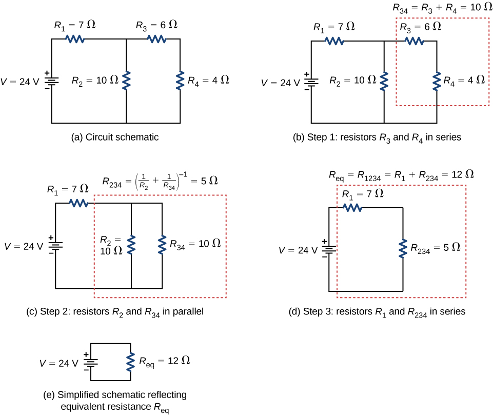
Series vs parallel part one duration. Parallel and series circuits james gill. Parallel speaker wiring combines all speakers positive speaker leads together and all negative speaker leads together. If you have the following circuit with 2 parallel components in series with a third resistive component we re going to consider the 4 ohm speaker to be purely resistive first you have to calculate the total resistance of the parallel section.
So if we were to use a 2100ma buckblock and have three parallel strings of 3 leds in series then the 2100ma would get divided by three and each series would receive 700ma. The common household circuits used in electrical wiring installation are and should be in parallel. Now we know that four speakers connected to one amplifier channel with series parallel wiring creates a 4 ohm load. The formular for series wiring is.
Parallel circuits are the simplest electrical circuit to wire. The drawing should look like figure 3c with the label 4 ohms in place of zt. Sketch a new one channel diagram showing the total equivalent load impedance.


